If you’ve worked with utility network data then you’re aware that it allows you to use associations to define the way that different features support, contain, or attach to one another. These associations act like relationships between features in many ways but also provide an additional capability that allows them to be automatically included in analysis when networks are traced or updated.
This article will show several examples of how associations can be used to solve common analysis workflows as well as how subnetworks can take advantage of associations for reporting purposes.
Trace Options
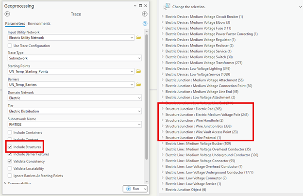
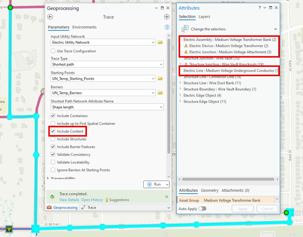
Let’s start by looking at how associations are included in analysis. In the parameters for tracing there are three options that allow you to include containers, content, and structures in your trace results.

Let’s look at workflows for each of these options.
In addition to this we will be discussing how to take advantage of these options when defining your subnetworks.
Joint Use Attachment
Most electric utilities that share a service territory with other utility companies participate in what is known as a Joint Use program. This is an agreement within an area that allows a utility company to attach equipment to a pole that isn’t theirs if they coordinate the work with the owner of the pole and fairly compensate them. These systems benefit everyone involved since they allow structures to be shared as communal property while ensuring that the companies that own and maintain the structures are fairly compensated for their investment.
To maintain this agreement and make it work there must be an up-to-date inventory of all structures and equipment in an area, along with a record of who owns which equipment, and what leasing agreements are in place. In general, these databases are well maintained, because all in the program are incentivized to keep accurate records, however, occasional auditing needs to be completed to ensure that no illegal attachments have been made and that new infrastructure is properly registered in the database. So, how can the utility network help with this?
This joint use assessment is often incorporated into inspection programs performed by utilities to inspect and maintain their circuits. Because the utility network models all the equipment and conductors attached to a pole, all you need to do to get the poles associated with a circuit is to run a trace for the circuit you are inspecting and choose the Include Structures option. Once you have all the poles in an area you can ensure that you have access to all the joint use attachment agreements for the structures in the area you will be inspecting.
Fats, Oils, and Grease
One of the challenges faced by organizations that manage sanitary sewer systems is how to manage the accumulation of fats, oils, and grease in their networks. Left unmitigated, this accumulation can cause blockages that can lead to backups or even sewage overflows. Effectively managing this problem requires collaboration between the organizations that create these discharges (restaurants, commercial manufacturing facilities, etc.) and the organizations that maintain the sanitary sewer system. Many organizations manage this problem by establishing a Fats, Oils, and Grease (FOG) program that works with local business to ensure they are installing and properly maintaining the equipment necessary to prevent or reduce the sediment buildup in the sanitary sewer system. However, when an issue arises and a blockage is identified, someone from the FOG team is tasked with investigating the cause.
This is another area where the utility network can assist. The first thing that the utility network can do is run an upstream trace to identify all the customers upstream of the blockage that participate in the FOG mitigation program. This trace can serve to not only identify the customers but also identify any FOG mitigation equipment that they maintain. There is a wide variety of equipment that can be used in a FOG mitigation program, but it is typically installed either underground or requires access to a special room in a building. By tracking the access locations in the GIS, and making them containers for the FOG equipment, we can use the Include Containers option as part of the trace to quickly identify whether the equipment is accessible via a nearby manhole or elsewhere at the customer site.

Available Conduit
When building underground infrastructure for use with electric and telecommunications it is common for organizations to create complex networks of vaults interconnected with multiple runs of conduit. Because building these networks involve significant amounts of work, most companies build extra capacity into the system in the form of spare runs of conduit so that all they need to do is run new cables through existing conduit when new construction occurs.
Utilities familiar with the utility network know that in addition to traditional tracing the utility network also allows you to trace your structure network. If your organization maintains a complex underground vault and conduit network, you can run a trace to identify a path between two points in that network.
When building out new construction it’s important to not only know that there is a path between two points, but you also need to know it has spare capacity. While it’s possible to manually track the availability of a conduit using an attribute, you can also answer the same question using a trace. By selecting the Include Content option when tracing your conduit network, you can not only see whether the conduit is occupied, but also which cables occupy those conduits. If your new project is large enough, like installing a new data center, you may even choose to reroute existing cables to make room for the new construction.
Subnetworks and Associations
Now that you’ve seen how associations can be used to enhance how you use GIS to perform analysis, let’s look at how the utility network allows us to manage this same information with subnetworks. When utilities manage their networks, they often organize them in smaller units that can be generically referred to as subnetworks. The utility network allows you to explicitly define subnetworks so that as data is modified the system will track which subnetworks are affected and will even populate attributes on features that indicate which subnetwork they belong to. What’s interesting is that this process also allows you to extend the subnetwork information to the features associated with the subnetwork by setting the trace configuration on a subnetwork to also include its containers and content.

When one of these options is selected while configuring the subnetwork definition for a tier, the structures and containers that support a subnetwork will also have their subnetwork information updated when they have attachments or content that belongs to a subnetwork. However, because the structures and containers don’t directly carry water, electricity, etc. the system will populate a Supporting Subnetwork Name field instead of the Subnetwork Name field used by features that participate in the subnetwork.
While not all organizations may want to maintain this information, it can also help with some of the workflows described above. In the joint use example, the Supporting Subnetwork Name field on a pole would list all the circuits that are attached to it.
In the FOG example we would be able to see the Sewershed and sub-basins associated with each manhole or access locations for FOG mitigation equipment. FOG equipment typically needs to be cleaned on a regular basis, and while this is the customer’s responsibility, a good FOG program includes a period inspection of equipment to ensure it is not only cleaned properly but that other preventative maintenance is occurring.
In the conduit example, you could see whether a conduit contains a cable by looking at its Supporting Subnetwork Name field instead of relying on a manually maintained availability field.
Conclusion
If you’re interested in learning more about tracing and analysis with ArcGIS Utility Network visit the Analysis and Tracing with ArcGIS Utility Network learning series. This series contains a collection of articles, videos, and tutorials to help familiarize you with tracing, subnetworks, and ArcGIS Utility Network.
If you have specific questions about how to solve different workflows, please visit us on the ArcGIS Utility Network channel on the Esri Community site. This is an active community with thousands of active members.


Commenting is not enabled for this article.